Its been a while since I've done an update, so though I'd do that now...
Since I saw 'Three More Words' play a while back at Fowlers, I've been reading up on guitar pedals. I the gig was at a Triple J band competition. There were a few interesting bands. My nephews played a good set, but to my ears at least, I think were let down by the guys on the mix desk. Other bands sounded good and were mixed very differently. Perhaps its as the lads intended, perhaps their pedals?
Any how, there is plenty to read on guitar pedals. A lot more than I expected anyway. There seems to be a religious divide between Hi-Z, unit gain, buffers/amps before pedal and not. Why is this so? I can only put it down to the desire for minimalism/simplicity and/or the old school. The reasons for using Hi-Z buffers and drivers sounds reasonable.
Anyhow, I think I'll do some more work with the audio oscillators and tinker a bit. Thinking about these things as audio 'filters'. I expect it can only help later with debugging AF blocks in radios.
Also on the bench is another lantern prototype. Needs a lot more work, but there is a 28 pin socket, RGB LEDs and associated stuff. Next to add is the ISM band qrpp radios and drop in the ATMEL328 and program it up. =)
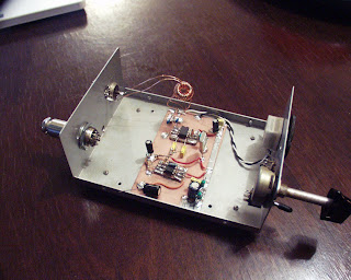
Along with an 80 meter receiver project. Using the shottky diodes and ferrite toroids in a component draws that I purchased at a club auction at least a month ago, I built up a doubly balanced mixer. Its now connected to the AF amp and LO on the direct conversion receiver. Now to finish the band pass filter and graft on an antenna input. I found the same circuit in 'Understanding Amateur Radio' from 1977.
So I wonder if this radio was put out as a paper or article by Wes Haywood around 1968? The one that George Dobbs found and built in 1968. In fact I wonder if this is the 'missing' direct conversion receiver that Bill Meara found back in the mid seventies and tried to build as a teenager?
Given I had a birthday recently, I'm inspired to build a radio that is vintage from around the year of my birth. Something designed in the late sixties or early seventies suits and using parts from the early seventies is what I'm aiming for. When I've upgrade my license I'll build a transmitter to match. I suppose it all depends on finding suitable parts, as leaded components are becoming harder and harder to find I might have to find some vintage kit to rebuild my project from. We shall see...
Last weekend I went to a 'zine workshop by the guys from Format. Yes thats how to make 'zines. Pronounced 'zeens'. Little homemade, often short booklets on all sorts of topics. Some examples of zines at the workshop were; mini comics, howtos, short stories, poems, lots of art and collage, just to name a few. I made a 'how to make a Pixie ][' on an A4 page folded to make 8 little pages. Worked out pretty well. Thinking about what other little projects; AF or RF kits, I can fit into that format. Or perhaps it might be better to get 8 A5 pages on two sheets of A4 folded in the middle... more options to explore. I think the first one needs to be about ugly and manhattan construction.
Oh and I picked up a 'little' oscilloscope. Should get in contact David Rowe and return the one I borrowed. Has been a wonderful tool to have. Looking forward to work on gear in the higher part of the HF bands.
Kim VK5FNET
Showing posts with label direct conversion receiver. Show all posts
Showing posts with label direct conversion receiver. Show all posts
Sunday, July 18, 2010
Monday, May 31, 2010
80 meter DC Rx - Debugging lack of mixing
Hit the issue with nothing coming out of the mixer. Using the signal injector feeding into the RF input port, I could hear RF static type noises.
So, I spoke to a few folks at the last AHARS meeting. Specifically what drive level from the LO is needed to turn on the 1N4148s. Jim, VK5TR suggests that I will need +7dB. Darryl, VK5JDS suggest about +6dB.
So I made an RF probe, a 10nF capacitor / 1N34 diode / 47M resistor style probe that I attached to the front of the DVM. A simple T shaped arrangement, on a little scrap of copper clad board and put a BNC socket on one end for a CRO probe, the other to a pair of banana plugs to attach to the DVM.
Wonderful; 0.4 volts from the LO. Now to match +7dB up to what volts output that should be...
72,
Kim VK5FNET
So, I spoke to a few folks at the last AHARS meeting. Specifically what drive level from the LO is needed to turn on the 1N4148s. Jim, VK5TR suggests that I will need +7dB. Darryl, VK5JDS suggest about +6dB.
So I made an RF probe, a 10nF capacitor / 1N34 diode / 47M resistor style probe that I attached to the front of the DVM. A simple T shaped arrangement, on a little scrap of copper clad board and put a BNC socket on one end for a CRO probe, the other to a pair of banana plugs to attach to the DVM.
Wonderful; 0.4 volts from the LO. Now to match +7dB up to what volts output that should be...
72,
Kim VK5FNET

Sunday, May 16, 2010
80 meter DC Rx - Debugging AF Amp


This morning I dug out the old signal injector, that I picked up at an auction a while back and proceeded to fumble my way around the AF Amp from the crystal ear piece back towards the input. Signal from the input of the PNP, but not from the input of the NPN. So out with the datasheet, original circuit diagram from G3RJV and my hand drawn copy. I was looking for mistakes in my copy again, when I noticed that the CBE notation on the PNP and NPN. I had correctly copied them down, but wondered if my implementation on the board was correct. The 2N3904 datasheet said no, I had swapped the C for E on the NPN... Fired up the soldering iron, and went off to make a cup of coffee. Ten minutes later I had the signal injector sending a wave through the whole amplifier now. Success at last!
So I reassembled the AF Amp board on the main board and turned it all on. Still no HF static, so I proceeded to poke around with the signal injector, when I put it on the antenna input I could hear some HF static. Well I think it is. It is quite possible that the RF oscillator isn't puting out enough power to turn on the diodes in the ring mixer. Now to make a RF power meter and test the mixer.
You will note in the images, the 'temporary' work bench with tools, the radio shack signal inject has been a good investment and the NPN transistor - 2N3904 - now in the correct orientation.
Kim VK5FNET
Monday, May 10, 2010
80 meter DC Rx step 3 - VFO built and working

Built up the VFO yesterday, put it on the frequency counter. Seems to even been in the right part of the band. I drew up the circuit on a little note pad, however I miss drew the tuning inductor and the tuning capacitors. So after assembling most of it, I thought that I would double check the original photo and noticed that my selection of capacitors was quite incorrect! The tap also needed extra reading, after I had to calculate the different number of turns from the original T68-2 to us a T50-2 instead. I had to unwind and add a tap six turns from the grounded end, worked it out in the end. Its stable enough once warm, although it was sitting on the washing machine with the back door open with a gentle breeze. I need to find some polystyrene glue or "Q Dope", I believe its called, for gluing the inductor windings. Now to build the filter and find why the AF amp isn't working.
Kim VK5FNET
Sunday, May 02, 2010
80 meter DC Rx step 2 - AF Amp


Spent a few hours drawing up and building the AF Amp for George Dobbs, 1968 80 meter receiver.
I now have a small board that I can mount inside a tin intended for the receiver. The tin is a bit smaller than A5 sized and about two inches high. The next couple of days should yield an oscillator. I never cease to be amazed at how the time flies when building...
Now moving on to test it. =)
Kim VK5FNET
Wednesday, April 21, 2010
80 meter DC Rx step 1 - Diode ring mixer


Decided to take a break from the QRSS Rx. Its doing _something_ but I don't know if its on frequency or if the bandpass filter is obliterating the incoming RF or if my antenna is really crap.
So I hunted around for another project to keep myself busy with in the mean time. Picked up a copy of Practical Wireless, February 2010. George Dobbs G3RJV, has a receiver first built in 1968 that he re-explores. An 80 meter DC Rx.
Thought it might be a simpler project to work my way through. Also if it pans out, would be good to take it along to the AHARS Show and Tell night.
We just had the AHARS Members Buy and Sell night, a week ago and I purchased a handful of T37's and T50's. This will help move along a bunch of projects I have been wanting to do for ages =)
So here is the first step, the diode ring mixer in the middle of the copper clad board...
I think I will put the band pass filter on one side and the oscillator on the other and shield them both. Then add the audio board on another copper clad board. Perhaps build it up in a Haighs tin...?
Kim VK5FNET
Sunday, April 11, 2010
just finished a colpits oscillator for the DC Rx

Spent a couple of enjoyable hours here on the workbench building up a colpits oscillator, which is very similar to the one recently build by Bill, N2CQR, see over at the SolderSmoke blog.
You can see the frequency counter, 10.13805 MHz. I spent some time mucking around with the variable capacitor in series with the crystal. At best all the options I had would move the rock up or down by 100Hz. Although later when I mounted the variable capacitor in parallel with the impedance matching transformer, I noticed that it would pull it a total of 4Khz. Not sure if this is the right way to tune it, but it seems to work for now. So set it up for 10.140MHz, assembled the LO board into the little case. Hooked the audio and power up to the peecee and fired up QRSS-VD.
So much noise! I turned off everything that I didn't absolutely need and went around rearranging cables. So now the capture is cleaner. However there don't appear to be any QRSS signals in the air ...
Will do more tinkering later and check the clipboard. May need to do a lot more work on the dipole.
Kim VK5FNET
Monday, April 05, 2010
QRSS receiver up and running
Well its taken a good long while, but I've finished off the QRSS receiver and have a grabber running. I'm not picking up any obvious signals. I have not checked the clipboard, but thought I'd tinker around anyway.
Seems to be something weird going on with the oscillator, I can't get the frequency counter to pick anything up under 66MHz, which is way out of the ball park. I noticed that when I bump the crystal or hold my finger on the crystal the capture changes significantly.
So may need to move the oscillator off the main board and box it up and put a high impedance buffer on it to be able to check the frequency with the external counter.
Seems to be something weird going on with the oscillator, I can't get the frequency counter to pick anything up under 66MHz, which is way out of the ball park. I noticed that when I bump the crystal or hold my finger on the crystal the capture changes significantly.
So may need to move the oscillator off the main board and box it up and put a high impedance buffer on it to be able to check the frequency with the external counter.
Monday, March 15, 2010
more work on the DC Rx
Spent several hours in the shack over the weekend. Heres the results;


Now need to add power, a 5V rail and the audio out.


Now need to add power, a 5V rail and the audio out.
Wednesday, March 10, 2010
I have mail
This afternoon I came home after work and pfaffed about a bit before realizing that I had not checked the mail. So I did.
I have a couple letters there, after discarding the twenty or so political spam, I found a letter from the ACMA and a hand addressed envelope that was rather battered. Seems to be a local specialty.
So I rushed inside and opened them all up. So I need to renew my license, its about that time. The second was from Terry. Now I was excited!
To my surprise, not one, but three T37 toroids were to be found inside! two -2's and a -6.
So over the next couple of days there will be some winding a happening for the BPF of the DC Rx!
Then perhaps a low pass filter for a Pixie2? Or perhaps I might make another from scratch and lay it up on a new board, smaller than the last. Or perhaps a doubly balanced mixer?
Kudos to Terry, now to get you back =)
I have a couple letters there, after discarding the twenty or so political spam, I found a letter from the ACMA and a hand addressed envelope that was rather battered. Seems to be a local specialty.
So I rushed inside and opened them all up. So I need to renew my license, its about that time. The second was from Terry. Now I was excited!
To my surprise, not one, but three T37 toroids were to be found inside! two -2's and a -6.
So over the next couple of days there will be some winding a happening for the BPF of the DC Rx!
Then perhaps a low pass filter for a Pixie2? Or perhaps I might make another from scratch and lay it up on a new board, smaller than the last. Or perhaps a doubly balanced mixer?
Kudos to Terry, now to get you back =)
Sunday, March 07, 2010
More work on QRSS DC Rx and a photo

Its been a slow week, been home crook most of it. Done a few odd jobs around the house and have been meaning to post this image for a few days. Made a saw horse for working with longer lengths of timber. Getting the paint striping out of the way, so we can repaint the study. Along with lots of reading.
Have added some more components to the QRSS DC Rx. Took this photo before adding the front end capacitors. Spent some time working out a replacement for the T37-6 transformer. Came to the conclusion that I couldn't do it with the materials that I have. Terry has come to the rescue however, he has just received a parcel of various toroids, transistors, etc. Terry has offered to send me one, so I am expecting one in the mail any day now =) This has been along time coming. Really looking forward to getting this rig on the air!
Ooops, just realised that I've not yet put on the feedback resistors... More work to go =)
72,
Kim VK5FNET
Monday, March 01, 2010
Making a band pass filter, or I hate toroids
I have made some progress on the NE602 direct conversion receiver. I have layed up most the components onto a copper clad board and I now need to add the band pass filter and the front end interface to connect up to an antenna.
I hit a similar problem with the Pixie2 I made previously. I don't have access to any of the named toroids that you find in the HAM radio journals and books. You know, names like T37-6. So I'm doing the numbers to try to lash up a air-space coil instead.
I'm reproducing the 30m QRSS Receiver as built by Hans Summers, G0UPL. Its a hardware defined radio that outouts audio to a peecee to decode.
I have a handful of plastic coil formers that appear to be 1/4" x 1". They have a fiber board on the bottom with five terminals to connect you inductor elements to and your pcb.
So using the calculator at kitsandparts I worked out that following table;
So I've spent half the day crunching the numbers to work out how to get an air-spaced to get the numbers to match the above... The numbers just don't work =/ I'm sure I'll find something and maybe I'll just have to put a bunch of cash aside and make an order to the US.
72,
Kim VK5FNET
I hit a similar problem with the Pixie2 I made previously. I don't have access to any of the named toroids that you find in the HAM radio journals and books. You know, names like T37-6. So I'm doing the numbers to try to lash up a air-space coil instead.
I'm reproducing the 30m QRSS Receiver as built by Hans Summers, G0UPL. Its a hardware defined radio that outouts audio to a peecee to decode.
I have a handful of plastic coil formers that appear to be 1/4" x 1". They have a fiber board on the bottom with five terminals to connect you inductor elements to and your pcb.
So using the calculator at kitsandparts I worked out that following table;
| Turns | Inductance |
| 2 | 0.01uF |
| 5 | 0.07uF |
| 35 | 3.67uF |
So I've spent half the day crunching the numbers to work out how to get an air-spaced to get the numbers to match the above... The numbers just don't work =/ I'm sure I'll find something and maybe I'll just have to put a bunch of cash aside and make an order to the US.
72,
Kim VK5FNET
Thursday, November 12, 2009
QRSS receiver crystal for 10 meters
The 28.188MHz crystal arrived today from Nick, VK1AA. Have been hanging out for it to arrive and would really like to get a receiver up and running.
This weekend looks like being a scorcher, about 38c, so a bit of indoors building will be in order. Which also leads one to think about oscillator stability. With night time temperatures of 15c to day time temperatures of 35+c degrees there is plent of room for drift.
Thoughts on work to do;
So, thoughts on work to be this weekend;
Doesn't sound like much on 'paper', but on top of the domestic chores should be a busy weekend.
72's
Kim - VK5FNET
This weekend looks like being a scorcher, about 38c, so a bit of indoors building will be in order. Which also leads one to think about oscillator stability. With night time temperatures of 15c to day time temperatures of 35+c degrees there is plent of room for drift.
Thoughts on work to do;
- An antenna for 10 meters; vertical or dipole?
- If heading down the di-pole route, balanced or OCFD?
- Maybe a balun?
- A transmission line should be straight forward, I have some spare clean RG-213.
- How about a tuner, then how do I measure if its really working?
- If a vertical, what about a copper cactus or a just a 5/8 vertical?
- Should I make the local oscillator in a separate box?
- If so I could drive the Kenwood to TX test ... wonder what specs are required to drive its VFO port?
- Then modify the 'sudden tunner' style DC receiver. Based on an NE602 and LM386.
- Hook up to peecee with 96KHz sound card.
- Grab with glfer or baudline.
- Announce its ready...
- Later develop something more focused around web based delivery.
- Find a design for a non-computer 'controlled beacon'. A condition of the Foundation Licence.
- Perhaps a beacon controller as simple as a pair of NE555's and a 4017. The first NE555 at a 30 second on/30 second off interval, driving the clock line of the 4017. The first output pin of the 4017 could then drive the second NE555 with a 3 second on/3second off interval. Effectively sending a '5' every ten minutes in QRSS 3 second dots. The '5' being from the call sign of VK5. My call sign being VK5FNET. But thats a job for another time, but would be nice to know what folks think...
So, thoughts on work to be this weekend;
- Get any antenna up
- Get a length of RG-213 terminated with PL259 connectors
- Blow the dust of my 4:1 balun I made some time back and check the connectors out
- Modify the 80m DC RX to run on 10m
- Patch up some audio cable for the DCRx to peecee sound card
- Work out how to capture images or do screen dumps from glfer
- Announce it...
Doesn't sound like much on 'paper', but on top of the domestic chores should be a busy weekend.
72's
Kim - VK5FNET
Monday, June 22, 2009
Repairs and receiver experimentation
Its been a while since there was some progress on the workbench. This last weekend kicked off by reassembling the frequency counter after re-soldering every joint on the board. It took about two hours to do, but it has all paid off, its now working comparing against a known working source.
I started tweaking the direct conversion receiver, with less success, but got to test out a number of other crystals along the way. 2MHz oscillates stably at 1.999999MHz, while the 25MHz crystal does not. I changed a number of different inductors and NPO capacitors to similar values to other circuits I've seen, but to no avail for 25MHz... So much for the idea of 25MHz +/- 3-4MHz VFO. There are plenty more options to come though. Found what looks like a pair of FT37-43's. Will have to check the datasheet but they look about the right size and came from a mystery box from a junk sale a while back. Will tinker with it some more.
The DC receiver picks up a lot of terrible noise around 1.8MHz which I assume is AM broadcast with the 2MHz crystal. Need to tinker more with that, and see if I can find a better way to link up the front end, not using a band pass filter to give me more tuning range. Not really sure how this works yet, but theres a lot of draw design found from the net and build. Probably hitting impedance mismatch issues. I'm sure I'll figure it out eventually.
I think its time to migrate the DC receiver from the breadboar to a manhattan board. I'm finding that the more I tinker with it the less it works. Probably connections of the components being dragged around by CRO probes, etc... Well its too colder to hang around in the radio shack any longer.
I started tweaking the direct conversion receiver, with less success, but got to test out a number of other crystals along the way. 2MHz oscillates stably at 1.999999MHz, while the 25MHz crystal does not. I changed a number of different inductors and NPO capacitors to similar values to other circuits I've seen, but to no avail for 25MHz... So much for the idea of 25MHz +/- 3-4MHz VFO. There are plenty more options to come though. Found what looks like a pair of FT37-43's. Will have to check the datasheet but they look about the right size and came from a mystery box from a junk sale a while back. Will tinker with it some more.
The DC receiver picks up a lot of terrible noise around 1.8MHz which I assume is AM broadcast with the 2MHz crystal. Need to tinker more with that, and see if I can find a better way to link up the front end, not using a band pass filter to give me more tuning range. Not really sure how this works yet, but theres a lot of draw design found from the net and build. Probably hitting impedance mismatch issues. I'm sure I'll figure it out eventually.
I think its time to migrate the DC receiver from the breadboar to a manhattan board. I'm finding that the more I tinker with it the less it works. Probably connections of the components being dragged around by CRO probes, etc... Well its too colder to hang around in the radio shack any longer.
Monday, June 08, 2009
mashup ideas: solar powered radio
From the maker blog a while back they ran a series of posts on joule theif.
Bill on the SolderSmoke blog ran a couple of articles on mechanically keyed transmitters, like the ET phone home rig, also a rew ideas around clock powered keying.
So my brain was buzzing away recently and it wasn't until I spotted the solar powered garden lights, that ceased to work a couple of months ago, that I thought about re-using them. The little solar cells only put out 0.8-1.1 volts. Three in series put out around 3.2 volts in full sun light. I need to go back and see what kind of current they can sink though...
To power something like an arduino keyed tx or a DC receiver with NE612, I would need a solid and regulated 5 volts.
It wasn't until this morning, on the irc channel of our local homebrewers, that I thought about mashing up the joule theif and the 80 meter DC receiver to make a solar powered radio =) It would make it limited to day light hours, but its certainly workable. Still have some other things to work on first, but certainly the next project on the list =)
Bill on the SolderSmoke blog ran a couple of articles on mechanically keyed transmitters, like the ET phone home rig, also a rew ideas around clock powered keying.
So my brain was buzzing away recently and it wasn't until I spotted the solar powered garden lights, that ceased to work a couple of months ago, that I thought about re-using them. The little solar cells only put out 0.8-1.1 volts. Three in series put out around 3.2 volts in full sun light. I need to go back and see what kind of current they can sink though...
To power something like an arduino keyed tx or a DC receiver with NE612, I would need a solid and regulated 5 volts.
It wasn't until this morning, on the irc channel of our local homebrewers, that I thought about mashing up the joule theif and the 80 meter DC receiver to make a solar powered radio =) It would make it limited to day light hours, but its certainly workable. Still have some other things to work on first, but certainly the next project on the list =)
Sunday, May 24, 2009
Progress on NE602 based direct conversion receiver
So today I stayed home due to brain pain, it had been building up for the last few days. Also I had difficulty with my balance. To the point that walking involved bumping into everything. Lots of water and pain killers helped a little, breakfast and coffee later helped a little too. However the head ache didn't wear off until late into the afternoon with more sleep. So I spent some of the day sitting down, tidying the shed.
The cool thing about that was I found a couple of little paper bags with parts that I had bought months back and promptly filed for safe keeping in boxes! Anyhow, that list of parts contained an SA602, 3.579MHz crystals, a variable poly-cap, a large breadboard and some zeners.
This was all the missing parts for the NE602 based direct conversion receiver I've been wanting to build. So late this afternoon I sorted out all the other parts, put them in a box and setup on the kitchen table to assemble. My soldering iron and other tools are currently at a friends, so I pretty much had to assemble everything up on the breadboard.

Made dinner, a tasty curry with shallot pancakes. Then assembled it as per the circuit from W1AW. I am not sure where I first found it, google has a few references to it about. There are also a few variations on the NE602 direct conversion receiver, like the MRX-40_Mini_Receiver and another that I like using LC tank circuits for both the RF input filter and the oscillator side.
I fired it up but heard absolutely nothing. Much comparing with the diagram led to adding the vcc and ground rail for the LM386, after which I could hear familiar hash with the speaker held very close to my ear. I dug out the Pixie2 hoping to create some kind of signal. However the oscillator from the Pixie2 did not create the expected signal or inteference on the DC receiver. So this needs looking at another day when I can focus for more than ten minutes at a time. Hopefully this coming weekend wont involve any more headaches.
Kim VK5FNET
The cool thing about that was I found a couple of little paper bags with parts that I had bought months back and promptly filed for safe keeping in boxes! Anyhow, that list of parts contained an SA602, 3.579MHz crystals, a variable poly-cap, a large breadboard and some zeners.
This was all the missing parts for the NE602 based direct conversion receiver I've been wanting to build. So late this afternoon I sorted out all the other parts, put them in a box and setup on the kitchen table to assemble. My soldering iron and other tools are currently at a friends, so I pretty much had to assemble everything up on the breadboard.

Made dinner, a tasty curry with shallot pancakes. Then assembled it as per the circuit from W1AW. I am not sure where I first found it, google has a few references to it about. There are also a few variations on the NE602 direct conversion receiver, like the MRX-40_Mini_Receiver and another that I like using LC tank circuits for both the RF input filter and the oscillator side.
I fired it up but heard absolutely nothing. Much comparing with the diagram led to adding the vcc and ground rail for the LM386, after which I could hear familiar hash with the speaker held very close to my ear. I dug out the Pixie2 hoping to create some kind of signal. However the oscillator from the Pixie2 did not create the expected signal or inteference on the DC receiver. So this needs looking at another day when I can focus for more than ten minutes at a time. Hopefully this coming weekend wont involve any more headaches.
Kim VK5FNET
Subscribe to:
Posts (Atom)